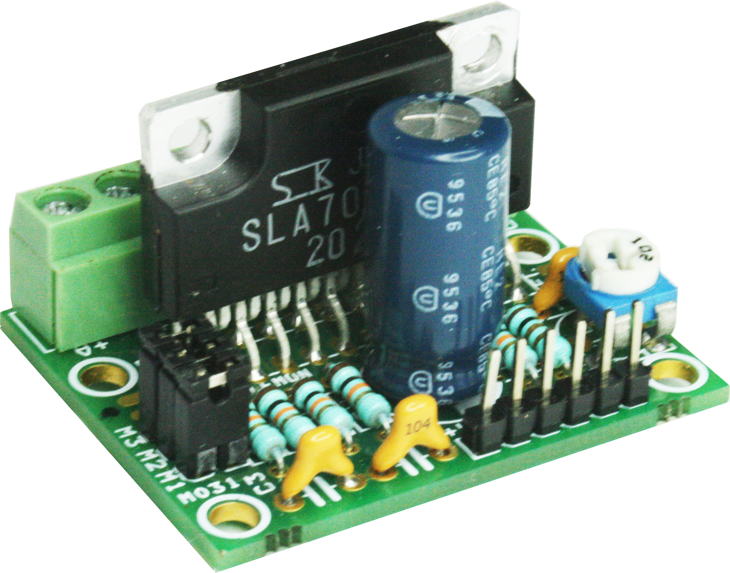
5 Phase Stepper Motor Driver Projects
5-Phase stepper motor drivers that operate in the pulse input mode and built-in controller mode are available. You can select a desired combination according to the. Hi, yesterday i bought some stepper motors '5 phase & 0.72 deg./pulse' i thought it would be good for the tolerance of the printer, but i am confused! How can i control them? Is there a specific controller for such a 3d printer, what shall i use?
Stepper Motor Controller STEPPER MOTOR CONTROLLER for this project from Talking Electronics for $25.00 plus postage. See more projects using PIC micros: '.' This project controls a stepper motor in full and half-step increments.

Stepper Motor Controller built on Experimenter PC board THE STEPPER MOTOR There are a number of stepper motors on the market and it takes a little bit of understanding to know how they work. The main difference is the number of coils and the way they are connected but there are also points to know to get the maximum torque. A STEPPER MOTOR A stepper motor consists of a number of stationary coils and these are turned on and pull a rotary magnet towards the coil. Set A Light 3d Studio Keygens. This action turns a shaft.

But you must turn the coils on and off at the right moment to create rotary movement. This requires an external circuit consisting of pulses and these pulses must contain voltage and current to deliver energy to the stepper motor.
To understand how a stepper motor works, you just need to know the fact that a coil will attract a magnet when a current flows and it will repel the magnet when the current flows in the opposite direction. 95 Me Keygen Rarity. In the following animation you can see an armature (rotor) being pulled around by turning on one or more coils. Note that 8 steps can be created with 4 coils by turning them on individually or in pairs: Here is another diagram to show how the rotor is moved by half-step intervals: UNIPOLAR ANIMATION The following animation shows a 6 wire stepper motor. It can be converted to a 5-wire stepper motor by connecting the two centre taps together to the positive supply.
The two ends of each winding are alternately grounded to reverse the direction of the field provided by that winding. The cross section shown is a 30 degree per step motor. Motor winding number 1 is distributed between the top and bottom stator pole, while motor winding number 2 is distributed between the left and right motor poles. The rotor is a permanent magnet with 6 poles, 3 south and 3 north, arranged around its circumference. As shown in the figure, the current flowing from the center tap of winding 1 to terminal 'a' causes the top stator pole to be a north pole while the bottom stator pole is a south pole. This attracts the rotor into the position shown.
If the power to winding 1 is removed and winding 2 is energised, the rotor will turn 30 degrees, or one step. By turning on two windings during part of the cycle, a half-step can be introduced. This is shown in the animation. It takes three complete cycles of the control system to turn this 6-pole rotor one revolution.